

HDMI is widely used for digital video transmission across displays, control systems, and embedded computing platforms. In industrial equipment, however, the interface must operate under conditions that are rarely considered in standard electronics environments.
Factory floors, outdoor control cabinets, marine installations, and mobile platforms expose equipment to pressure washdown, salt fog, continuous vibration (5–20 Grms), and temperature cycles ranging from –40 °C to +85 °C. These conditions place mechanical and electrical stress on connectors, cables, and equipment ports that standard HDMI implementations are not designed to withstand.
Without proper sealing, retention, and strain management, HDMI connections in these environments can experience intermittent signal loss, connector fatigue, and premature interface failure, resulting in unplanned maintenance and system downtime.
This article explains the HDMI interfaces used in industrial systems, covering cable categories, connector formats, and port designs. It also highlights the limitations of standard HDMI implementations and the critical factors industrial engineers must understand when specifying HDMI for reliable operation in demanding environments.
Key Takeaways
Before specifying HDMI for industrial deployment, these are the decisions that most often determine whether the interface survives in service:
- Consumer-grade HDMI cables, including Standard, Premium High Speed, and Ethernet variants, are not industrially validated.
- Ultra High Speed (48 Gbps) is the minimum viable category for industrial deployment, with Active Optical required for runs beyond 10m or high-EMI environments.
- PCB-mounted receptacles fail at pull forces above 20N. Panel or bulkhead mounting is required in any installation subject to vibration, cable movement, or repeated mating cycles.
- Mating cycle rating must match the service interval: 5,000 cycles for fixed installations, 10,000 for periodic service access, and 50,000 cycles for test equipment or frequent unmating with hard gold plating.
- IP rating must match the actual exposure protocol: IP67 for occasional washdown, IP68 for continuous submersion, and IP69K for steam cleaning at 80 bar and above. Over-specifying increases mating force and accelerates seal wear.
What are HDMI Interface Variations in Industrial Systems?
In industrial equipment, HDMI reliability depends on more than connector size or bandwidth, because mechanical load, enclosure design, and environmental exposure directly affect connection stability over time. As a result, the interface is best evaluated across three technical layers: connector format, equipment-side port construction, and the operating environment.
The following sections examine these categories and their engineering implications:
- HDMI cable types manage signal integrity, attenuation, skew, and crosstalk across distance.
- HDMI connector types determine mechanical retention, contact reliability, and shielding effectiveness.
- HDMI port types define how the interface integrates with enclosures, governing load transfer and environmental sealing.
HDMI Cable Categories for Industrial Specification
Industrial HDMI performance is shaped by signal loss, EMI exposure, and mechanical stress, which limits the number of cable categories that can maintain reliable operation. In practice, three cable types define most industrial specifications.
The table below compares the primary HDMI cable types used in industrial systems.
| Cable Category | Bandwidth | Core Application | Industrial Relevance |
| Ultra High Speed HDMI | 48 Gbps | 4K@120Hz, 8K@60Hz, HDR | Supports high-resolution HMIs, where higher bandwidth prevents signal degradation in electrically noisy environments. |
| High-Speed Industrial HDMI | 10.2 Gbps | Industrial control panels, outdoor enclosures, HMI displays | Uses stranded copper conductors and a TPU jacket for flex-cycle resistance, chemical protection, and sub-zero durability. |
| Active Optical HDMI (AOC) | 48 Gbps | Long-distance, high-EMI environments | Uses fibre transmission, eliminating EMI susceptibility and enabling stable performance over long cable runs up to 100 m. |
1. Ultra High Speed HDMI Cable
Ultra High Speed cables require enhanced shielding with a triple-layer construction (foil + braid + foil) to maintain signal integrity near variable-frequency drives (VFDs), welding equipment, and RF systems.
Three signal integrity parameters determine whether a cable remains viable at the 6 GHz ceiling: insertion loss, pair skew, and impedance, each of which compounds over cable length if out of tolerance.
- Insertion loss: Less than 12 dB at 6 GHz (the HDMI 2.1 clock frequency ceiling; exceeding this causes pixel errors at high resolutions).
- Skew between pairs: Less than 150 ps/m (inter-channel timing misalignment above this threshold produces image artefacts at 4K@120Hz and above).
2. High-Speed Industrial HDMI Cable
High-speed industrial cable bandwidth is limited to 10.2 Gbps, sufficient for 1080p and 4K@30Hz. The construction specification addresses mechanical durability requirements that consumer cable grades do not meet:
- Conductor: Stranded copper (19x0.16mm) versus solid-core, which is critical for flex-cycle resistance in applications subject to repeated movement or vibration.
- Jacket compound: TPU versus PVC; TPU retains flexibility and chemical resistance below -20°C, where PVC becomes brittle.
This cable type is suited to installations where legacy 1080p display resolution is acceptable and mechanical durability is the primary constraint — such as industrial control panels, outdoor enclosures, or environments with exposure to oils, solvents, or wide temperature variation.
3. Active Optical HDMI (AOC)
An active optical cable converts electrical signals to optical transmission at the connector housing. OM3 multimode fibre carries the FRL (Fixed Rate Link) data signal. If the cable supports both HDMI 2.0 and 2.1, depending on the HDMI version, fibre carries either TMDS or FRL signalling. The conversion is internal, and the connector interface remains standard HDMI Type A.
Industrial advantages over copper:
- EMI immunity: Fibre is not susceptible to electromagnetic interference, eliminating ground loops between the source and display.
- Galvanic isolation: No electrical path between source and display enclosures, which is relevant for panels near high-voltage equipment.
Routing: Significantly reduced weight and smaller cross-section simplify cable tray management and enclosure entry routing compared to copper assemblies.
HDMI Connectors Variants Used in Different Devices
HDMI connector types refer to the physical plug formats defined by size and pin configuration. In industrial equipment, connector selection focuses on retention strength, mating durability, and vibration resistance rather than on form factor alone.
The table below compares the primary HDMI connector formats based on size, retention strength, and their practical suitability in industrial environments.
| Parameter | Type A (Standard) | Type C (Mini) | Type D (Micro) |
| Body dimensions | 13.9 x 4.45mm | 10.42 x 2.42mm | 6.4 x 2.8mm |
| Retention force (IEC 61169-29) | 10N minimum | 7N minimum | 5N minimum |
| Mating cycles (consumer grade for Type A) | 10,000 | 5,000 | 3,000 |
| PCB footprint | 20 x 11mm | 14 x 7.5mm | 9 x 5mm |
| Industrial viability | Moderate (with locking) | Low | Not recommended |
1. HDMI Type A Connector (Standard HDMI)
The full-size format is used in industrial displays, HMIs, and control panels. The 10N retention force provides adequate contact reliability under moderate vibration when specified with appropriate locking hardware.
Standard Type A connectors have known limitations in harsh environments, but each can be addressed through the right specification choices.
- Friction-based retention allows micro-movement between contact surfaces under vibration, leading to fretting corrosion over time. This is mitigated by specifying locking HDMI variants with screw-lock or push-pull latching, which increases retention force to 50N or above.
- Sealing is not built into the connector itself, as it is handled at the port level, which means enclosure design carries the responsibility for environmental protection.
- Cable strain transfers directly to the PCB mount unless the connector is panel-mounted with independent strain relief, making the mounting method a critical decision early in the design process.
2. HDMI Type C Connector (Mini HDMI)
The Mini HDMI connector retains the full 19-pin configuration in a more compact form factor, making it an option where board space is limited. However, the 7N retention force is marginal for vibration environments, and the smaller contact area increases resistance variation.
These constraints shape where Type C can be reliably specified:
- Fixed industrial equipment: Type C connectors are generally unsuitable in systems exposed to sustained mechanical stress, because lower retention strength increases the risk of contact instability over time. In these cases, Type A connectors with locking mechanisms provide more reliable long-term performance.
- Portable or embedded equipment: Type C connectors remain viable in space-constrained designs, provided additional strain relief and enclosure-level protection are used to compensate for reduced mechanical retention.
3. HDMI Type D Connector (Micro HDMI)
The Micro HDMI connector is designed for highly constrained board layouts where space is the primary driver. With a 5N retention force and reduced contact area, it is mechanically the weakest of the three formats and is generally insufficient for most industrial applications.
Where space constraints make it unavoidable, the following limitations should be factored into the design:
- It should be restricted to static installations with no vibration and low mating cycle frequency, as the reduced retention force makes it vulnerable to loosening and contact degradation in any dynamic environment.
- Dedicated cable strain relief is required in all installations to prevent the connector body from bearing cable load directly.
- The 3,000-cycle mating rating is the lowest of any HDMI format, making it unsuitable for applications that require frequent disconnection or periodic maintenance access.
For installations where the environment demands more, Bulgin's sealed HDMI connector range addresses the mechanical and environmental gaps that standard connector formats cannot close. Download the Bulgin catalogue to review sealed HDMI connector options and specifications.
How HDMI Ports are Implemented on Devices
HDMI port types describe the equipment-side interface where the connector terminates. Port construction influences how the interface withstands certain mechanical stress, determines enclosure mounting requirements, and affects environmental sealing in industrial and outdoor systems.
The table below compares the three port mounting configurations by load path, environmental protection, and typical industrial application. Below are the main HDMI port types used in equipment design:
| Port Type | Mounting | Load Path | Environmental Protection | Typical Application |
| PCB-mounted | Direct to the circuit board | Solder joints, traces | None (depends on enclosure) | Internal electronics, protected environments |
| Panel-mounted | Chassis/panel bulkhead | Enclosure metal | Gasket dependent | Control panels, HMIs, moderate exposure |
| Sealed panel-mounted | Chassis with integrated sealing | Enclosure metal | IP67/IP68/IP69K integrated | Outdoor, marine, washdown environments |
1. PCB-Mounted Port
PCB-mounted ports are the most common configuration in consumer-grade and embedded systems, where the HDMI receptacle is terminated directly to the PCB and the connector body protrudes through the enclosure cutout.
In protected industrial environments, this approach remains practical because the enclosure absorbs external mechanical loads, and cable movement is limited. As a result, mechanical stress does not transfer significantly to the connector interface, which allows PCB-mounted configurations to remain a cost-effective solution when access is infrequent and environmental exposure is controlled.
- Load path: Cable strain and vibration transfer directly to solder joints, with a typical pull-force rating of 20N before pad lift or trace cracking. Cable strain relief should be implemented independently at the enclosure entry point to keep mechanical load away from the solder joints entirely.
- Thermal stress: Cycling causes CTE mismatch between the connector shell and PCB, progressively stressing solder joints over service life, making this configuration less suitable for equipment exposed to wide temperature swings.
2. Panel-Mounted Port
The receptacle mounts to the enclosure metal via a threaded body or snap-fit, with an internal pigtail or short PCB connection.
Mechanical characteristics:
- Load path: Cable pull force (50N and above) transfers to the enclosure rather than the PCB, eliminating solder joint stress.
- Rotation resistance: Anti-rotation features (hexagonal flats, locking tabs) prevent nut loosening from cable torque under vibration.
- Environmental protection: Gasket dependent; sealing performance is determined by enclosure interface, not the connector itself.
In industrial environments, vibration can gradually loosen mounting hardware. Using thread‑locking compounds or serrated flanges helps maintain secure connections, while gasket materials should always be chosen to suit the specific environmental conditions.
3. Sealed Panel-Mounted Port
Sealed panel‑mounted ports are used where HDMI connections must pass through an enclosure while remaining protected from harsh environmental exposure. These ports integrate environmental sealing at both the panel interface and the cable entry point, typically using O‑rings or gaskets, with IP ratings validated to IEC 60529 and ISO 20653.
Mechanical characteristics:
- Sealing geometry: O‑rings compress against the panel face during installation, while the cable entry seal closes around the cable jacket outer diameter.
- Environmental protection: Rated to IP67, IP68, or IP69K depending on seal construction and intended exposure.
Industrial Use Cases for HDMI Connector Types
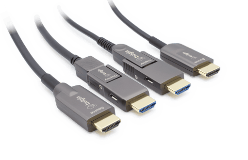
HDMI connector types are used across industrial systems that require reliable video transmission. Each environment places distinct demands on retention strength, sealing, and mating frequency, which is why connector format cannot be treated as a one-size decision.
The following applications illustrate where connector choice plays a critical role:
- Industrial Automation HMIs and Displays: Used in factory control panels and machine interfaces where connectors are exposed to repeated access and long operating hours.
- Medical Imaging and Diagnostic Equipment: Applied in imaging and monitoring systems that require stable video output and secure connections within controlled environments.
- Marine Navigation and Onboard Displays: Used in navigation and control systems exposed to humidity, salt air, and continuous motion.
- Outdoor Kiosks and Transport Infrastructure: Deployed in ticketing systems and public displays exposed to weather, dust, and temperature variation.
- Test and Measurement Equipment: Used in lab and field instruments where frequent connection cycles and physical handling are expected.
How to Select HDMI Connectors for Industrial Use
HDMI connector selection often fails when form factor or bandwidth is considered first, while installation stress and enclosure constraints remain unexamined. Successful deployment requires evaluating retention strength, mounting method, sealing requirements, and cable strain conditions during the initial design stage.
1. Evaluate the Operating Environment
Define the full exposure profile before selecting any component. Three categories must be documented:
- Dust type (conductive or non-conductive) and concentration class per ISO 14644-1.
- Humidity range, condensation cycles, and immersion depth or duration requirements.
- Cleaning agents (pH and concentration), oils, and solvents contacting the connector body or seal.
2. Review Mating Cycle Requirements
Contact plating thickness determines cycle life, and ratings should be matched to the actual service interval rather than the consumer-grade minimum.
The table below outlines typical mating cycle requirements based on application type and corresponding contact plating thickness.
| Application | Minimum Cycle Rating | Contact Plating |
| Fixed installation, rare access | 5,000 cycles | 0.38 micron Au/Ni |
| Periodic service access | 10,000 cycles* | 0.76 micron Au/Ni |
| Test equipment, frequent mating | 50,000 cycles | 1.27 micron Au/Ni or hard gold |
*These values represent minimum validated industrial targets and should be confirmed against the component datasheet rather than assumed from consumer-grade specifications.
3. Align With System Lifecycle and Maintenance Access
Connector reliability must align with the system’s intended service life, because premature degradation at the interface can drive unplanned maintenance and increase downtime. In practice, this means MTBF values need to be considered in the context of actual operating conditions rather than idealised laboratory ratings.
- Service interval alignment: For systems designed with a 10-year operational life and 5-year maintenance cycles, connectors typically require validated operation in the range of 50,000 hours to avoid mid-cycle replacement.
- Environmental conditions: MTBF values vary significantly with temperature, humidity, and mechanical stress, which means ratings should reflect real operating environments rather than standard test conditions.
- Failure impact: When connector degradation occurs before the system reaches its intended service life, it introduces unplanned maintenance events and increases overall downtime cost.
How Bulgin Supports HDMI Connectivity in Harsh Environments
As HDMI‑equipped designs move from prototype to production, engineers often encounter sourcing challenges. Consumer‑grade connectors may change revisions, disappear from supplier catalogues, or lack consistent panel‑mount options. Long‑term reliability, therefore, depends on HDMI interfaces with controlled product lifecycles, reliable availability, and well‑documented mechanical compatibility for extended production runs.
Bulgin supports HDMI connectivity through standardised sealed connector platforms and compatible active optical cable solutions that provide consistent mechanical interfaces and reliable component availability for long production cycles.
Here are the HDMI solutions Bulgin offers:
- 30 Series Waterproof HDMI: IP67-sealed, depending on the model, HDMI connector system combining sealed cables, dust caps, and a panel-mount coupler for exposed industrial installations.
- 6000 Series HDMI Buccaneer: IP68 and IP69K rated HDMI connectors, depending on the model, with a 30-degree twist-lock mechanism, providing fast mating and secure retention in wash-down environments.
- Standard Series HDMI Buccaneer: Proven waterproof circular HDMI connectors rated to IP68 and IP69K, supporting HDMI 2.1 performance across industrial and outdoor digital display applications.
- AO Series – Active Optical HDMI: Active optical HDMI cable assemblies using fibre optic technology for long-distance, high-bandwidth transmission with reduced electromagnetic interference, available in standard and armoured cable HDMI 2.1 variants.
With over a century of engineering experience, Bulgin provides sealed HDMI connectors and cable solutions trusted in demanding industrial, marine, and transport & infrastructure applications.
Conclusion
Industrial display systems continue to push toward higher resolutions, longer cable runs, and more compact enclosure designs, increasing the mechanical and signal integrity demands placed on HDMI interfaces. Connector selection, therefore, depends on more than size or bandwidth. Mounting method, cable category, environmental protection, and service life alignment all influence long-term reliability.
Bulgin supports these requirements through sealed HDMI connectors, locking interface variants, and active optical cable solutions. These solutions allow engineers to maintain stable HDMI connectivity across environments where enclosure protection, cable distance, and mechanical stability shape system performance.
Contact us to review HDMI connector and cable solutions suited to your environmental and performance requirements.
Frequently Asked Questions
Can HDMI be used alongside other industrial protocols on the same cable tray?
HDMI cables carrying high-frequency TMDS signals are susceptible to crosstalk from adjacent power cables, VFD outputs, and motor drive wiring routed in the same tray. A separation distance of at least 200mm is recommended between HDMI and unshielded power conductors, with a grounded metallic divider where physical separation is not achievable. Active optical cables eliminate this constraint entirely since fibre is immune to electromagnetic coupling, making AOC the practical choice when cable tray segregation cannot be guaranteed during installation.
Can active optical HDMI cables be used with sealed HDMI connectors?
Active optical HDMI cables are commonly used for long cable runs and can be combined with sealed connector interfaces at enclosure entry points to balance distance requirements with environmental protection. Verify that the AOC assembly's connector housing is mechanically compatible with the sealed panel-mount receptacle before specifying — housing OD tolerances vary between manufacturers.
What is the minimum bend radius to maintain signal integrity in industrial HDMI cable runs?
Are armoured HDMI cables necessary in industrial installations?
How does panel mounting affect serviceability and maintenance access in industrial equipment?
Panel-mounted HDMI connectors allow cable replacement and connector inspection without opening the equipment enclosure, reducing service time in fixed installations. The threaded body requires torque verification at each maintenance interval to confirm retention against loosening, and the gasket condition should be inspected for compression set if the installation involves thermal cycling or chemical exposure.